
Tip
See our video guides for quick tutorials that walk you through Sigmacalx basic functionalities and concepts. This is the easiest and quickest way to get going with Sigmacalx forms.
The Lamé Equations for the radial and hoop stresses of the pipe are based on the three-dimensional quations of equilibrium for a linear elastic cross section. As such these equations are triaxial equations and provide the most accurate calculation of pipe stresses. Two equations are provided:
In addition we added another equation for allowable tensile force of the pipe body at yield.
Formulas to calculate those stresses are taken from API 5C3 standard (A.2), and are valid for "thick-walled" pressure vessels with their wall thickness greater than one-tenth of the overall diameter.
Yield design equation, special case for capped-end conditions.
A design equation for initial yield of the pipe body with capped-end conditions and using the Lamé Equations for the radial and hoop stresses.
When you navigate to the Capped-end Conditions page, you will come across a button: These button allows you to include up to 20 distinct pipe specifications. By incorporating multiple pipes into the plot, you can conveniently compare them to one another, enabling the observation of boundaries and safe regions. An example illustrating this can be seen in Figure 23.
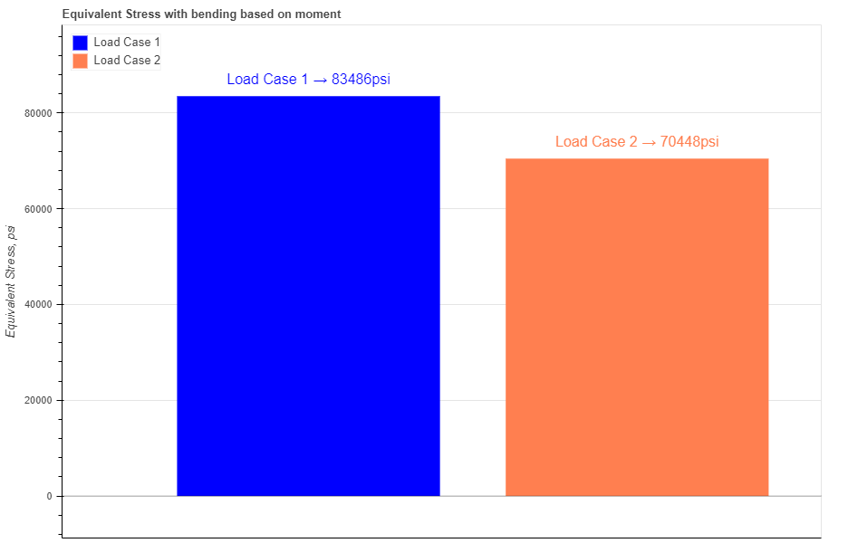
Figure 23: Two maximum internal pressures are presented as graphical bars based on the pipe specifications.
Hovering your cursor over any of these bars reveals headers specific to each pipe. The description labeled "Max Internal Pressure" indicates the absolute maximum of internal pressure should be applied for the specific pipe.
In the pipe section you have 3 required parameters: Outside Diameter (OD), Inside Diameter (ID) and specified minimum yield strength (YS)
There are 3 more optional parameters you may input on the tubing section: minimum Wall Thickness (mWT), Corrosion Allowance (CA) and Factor of the Pipe Wall (k_wall). The parameters Minimum Wall Thickness (mWT) and Factor of the Pipe Wall (k_wall) essentially represent the same concept, only utilizing different units. If you prefer to input the Minimum Wall Thickness (mWT), there's no need to input the Factor of the Pipe Wall (k_wall), and vice versa. Units for mWT is % and it is based on the specified manufacturing tolerance. Common number which is used for tubing and casing in the oil industry is 87,5%. Units for CA are either in or mm, depending which system you choose by pressing buttons Corrosion allowance is a measurement to the thickness of the wall. It is a metal loss throughout the lifespan of certain material in a certain conditions.
When you fill in all parameters for the pipe, press button. It is also a good practice to give a specific name for the pipe, for example: Tubing 7"-46#. This name will be shown on the generated report and on the selection menu in the load section.
You can customize each bar on the plot by changing the specific parameters under button. Here you can choose a color, opacity and show the label for each pipe.
After you enter the required data for your analysis you can generate the report by pressing button. There you can fill the Project Name, Document Number, Created by and your Company Logo. You can also leave those fields blank and our company logo will be set on the report. To download the report you need to press button again. At the bottom of the export pop-up window you will find two html links. The first link is to download the report in PDF format and the other link is to download HTML plot, that might be useful to observe if you have high density data.
Below you may watch a short video tutorial of how to use the forms of this particular calculation.
Video: 13 Capped-end Conditions manual
Yield design equation, special case for open-end conditions with zero external pressure and axial load.
A design equation for initial yield of the pipe body with open-end conditions and using the Lamé Equations for the radial and hoop stresses.
When you navigate to the Open-end Conditions page, you will come across a button: These button allows you to include up to 20 distinct pipe specifications. By incorporating multiple pipes into the plot, you can conveniently compare them to one another, enabling the observation of boundaries and safe regions. An example illustrating this can be seen in Figure 24.
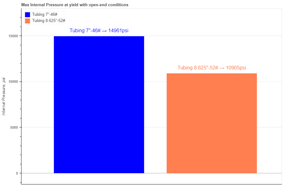
Figure 24: Two maximum internal pressures are presented as graphical bars based on the pipe specifications.
Hovering your cursor over any of these bars reveals headers specific to each pipe. The description labeled "Max Internal Pressure" indicates the absolute maximum of internal pressure should be applied for the specific pipe.
In the pipe section you have 3 required parameters: Outside Diameter (OD), Inside Diameter (ID) and specified minimum yield strength (YS)
There are 3 more optional parameters you may input on the tubing section: minimum Wall Thickness (mWT), Corrosion Allowance (CA) and Factor of the Pipe Wall (k_wall). The parameters Minimum Wall Thickness (mWT) and Factor of the Pipe Wall (k_wall) essentially represent the same concept, only utilizing different units. If you prefer to input the Minimum Wall Thickness (mWT), there's no need to input the Factor of the Pipe Wall (k_wall), and vice versa. Units for mWT is % and it is based on the specified manufacturing tolerance. Common number which is used for tubing and casing in the oil industry is 87,5%. Units for CA are either in or mm, depending which system you choose by pressing buttons Corrosion allowance is a measurement to the thickness of the wall. It is a metal loss throughout the lifespan of certain material in a certain conditions.
When you fill in all parameters for the pipe, press button. It is also a good practice to give a specific name for the pipe, for example: Tubing 7"-46#. This name will be shown on the generated report and on the selection menu in the load section.
You can customize each bar on the plot by changing the specific parameters under button. Here you can choose a color, opacity and show the label for each pipe.
After you enter the required data for your analysis you can generate the report by pressing button. There you can fill the Project Name, Document Number, Created by and your Company Logo. You can also leave those fields blank and our company logo will be set on the report. To download the report you need to press button again. At the bottom of the export pop-up window you will find two html links. The first link is to download the report in PDF format and the other link is to download HTML plot, that might be useful to observe if you have high density data.
Below you may watch a short video tutorial of how to use the forms of this particular calculation.
Video: 14 Open-end Conditions manual
Yield design equation generating the maximum tensile force for a pipe cross-section, with zero external and internal pressures.
When you navigate to the "Allowable Tensile Force" page, you will come across a button: These button allows you to include up to 20 distinct pipe specifications. By incorporating multiple pipes into the plot, you can conveniently compare them to one another, enabling the observation of boundaries and safe regions. An example illustrating this can be seen in Figure 25.
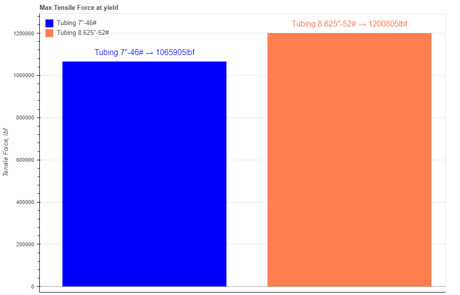
Figure 25: Two maximum tensile forces are presented as graphical bars based on the pipe specifications.
Hovering your cursor over any of these bars reveals headers specific to each pipe. The description labeled "Tensile Force" indicates the absolute maximum of axial load should be applied for the specific pipe.
In the pipe section you have 3 required parameters: Outside Diameter (OD), Inside Diameter (ID) and specified minimum yield strength (YS)
There are 3 more optional parameters you may input on the tubing section: minimum Wall Thickness (mWT), Corrosion Allowance (CA) and Factor of Safety (SF). Introducing a safety factor reduces the maximum tensile load by that factor. Units for mWT is % and it is based on the specified manufacturing tolerance. Common number which is used for tubing and casing in the oil industry is 87,5%. Units for CA are either in or mm, depending which system you choose by pressing buttons Corrosion allowance is a measurement to the thickness of the wall. It is a metal loss throughout the lifespan of certain material in a certain conditions.
When you fill in all parameters for the pipe, press button. It is also a good practice to give a specific name for the pipe, for example: Tubing 7"-46#. This name will be shown on the generated report and on the selection menu in the load section.
You can customize each bar on the plot by changing the specific parameters under button. Here you can choose a color, opacity and show the label for each pipe.
After you enter the required data for your analysis you can generate the report by pressing button. There you can fill the Project Name, Document Number, Created by and your Company Logo. You can also leave those fields blank and our company logo will be set on the report. To download the report you need to press button again. At the bottom of the export pop-up window you will find two html links. The first link is to download the report in PDF format and the other link is to download HTML plot, that might be useful to observe if you have high density data.
Below you may watch a short video tutorial of how to use the forms of this particular calculation.
Video: 15 Allowable Tensile Force manual