
Tip
See our video guides for quick tutorials that walk you through Sigmacalx basic functionalities and concepts. This is the easiest and quickest way to get going with Sigmacalx forms.
Three different approaches are taken into consideration when calculating the minimum collapse strength for a pipe body. Each of them has its own methods and equations to prevent collapse failure within the external pressure exceeding internal pressure.
These approaches are:
Formulas to calculate those collapse limits are taken from different standards API 5C3 and ASME.
The collapse design equation is intended for load cases when the external fluid pressure exceeds internal fluid pressure. A convenient, theoretically rigorous equation for cross-sectional collapse of a tube that accounts for realistic imperfections does not currently exist. The approach taken here combines theoretical, numerical and statistical tools.
The minimum collapse strength for pipe is given by a series of equations depending on the specific minimum yield and cross-sectional dimensions of the tube body.
These sub-equations are:
Formulas to calculate those collapse limits are taken from API 5C3 standard (8.4).
When you navigate to the "External Pressure Resistance-API" page, you will come across a button: These button allows you to include up to 20 distinct pipe specifications. By incorporating multiple pipes into the plot, you can conveniently compare them to one another, enabling the observation of boundaries and safe regions. An example illustrating this can be seen in Figure 26.
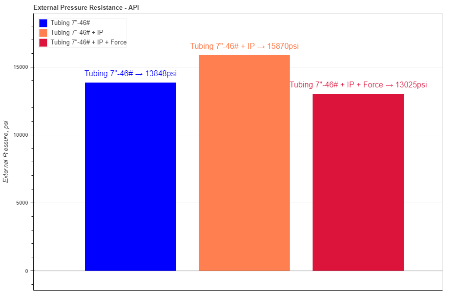
Figure 26: Three maximum collapse pressures are presented as graphical bars based on the pipe specifications.
Hovering your cursor over any of these bars reveals headers specific to each pipe. The description labeled "Equation" indicates the type of the equation is taken into account during calculation.
In the pipe section you have 3 required parameters: Outside Diameter (OD), Inside Diameter (ID) and specified minimum yield strength (YS)
There are 4 more optional parameters you may input on the tubing section: minimum Wall Thickness (mWT), Corrosion Allowance (CA), internal pressure (IP) and axial force (Force). Last two field allow you to input the influence of internal pressure and axial stress on collapse. Force value can be either positive (tension) or negative (compression). Units for mWT is % and it is based on the specified manufacturing tolerance. Common number which is used for tubing and casing in the oil industry is 87,5%. Units for CA are either in or mm, depending which system you choose by pressing buttons Corrosion allowance is a measurement to the thickness of the wall. It is a metal loss throughout the lifespan of certain material in a certain conditions.
When you fill in all parameters for the pipe, press button. It is also a good practice to give a specific name for the pipe, for example: Tubing 7"-46#. This name will be shown on the generated report and on the selection menu in the load section.
You can customize each bar on the plot by changing the specific parameters under button. Here you can choose a color, opacity and show the label for each pipe.
After you enter the required data for your analysis you can generate the report by pressing button. There you can fill the Project Name, Document Number, Created by and your Company Logo. You can also leave those fields blank and our company logo will be set on the report. To download the report you need to press button again. At the bottom of the export pop-up window you will find two html links. The first link is to download the report in PDF format and the other link is to download HTML plot, that might be useful to observe if you have high density data.
Below you may watch a short video tutorial of how to use the forms of this particular calculation.
Video: 16 External Pressure Resistance - API manual
Calculated value of maximum allowable external working pressure for the assumed value of minimum required thickness of cylindrical shell or tube, or spherical shell.
Calculations are based on factors A or B from subpart 3 in ASME BPVC.II.D.C.2021.
Formulas to calculate those design pressure limits are taken from UG-28 in ASME BPVC.VIII.1 standard.
When you navigate to the "External Pressure Resistance-ASME" page, you will come across a button: These button allows you to include up to 20 distinct pipe specifications. By incorporating multiple pipes into the plot, you can conveniently compare them to one another, enabling the observation of boundaries and safe regions. An example illustrating this can be seen in Figure 27.
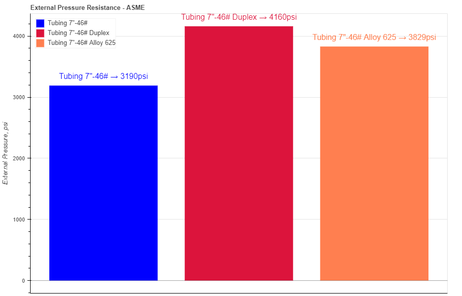
Figure 27: Three maximum allowable external working pressures are presented as graphical bars based on the pipe specifications.
Hovering your cursor over any of these bars reveals headers specific to each pipe. The description labeled "AEWP" indicates the allowable external working pressure. Ensure that this pressure value is not the total collapse pressure, as calculated in the API tab above, but rather the maximum working pressure in accordance with the ASME code.
In the pipe section you have 6 required parameters: Outside Diameter (OD), Inside Diameter (ID), Elastic Modulus at design temperature (EM), design length of a tube of a tube section between lines of support (LEN), type of material used to determine factors A and B (Type of Material), temperature to which the material is exposed (Temp). See figures in subpart 3 in ASME BPVC.II.D.C.2021 for a particular material and temperature for reference.
There are 2 more optional parameters you may input on the tubing section: minimum Wall Thickness (mWT) and Corrosion Allowance (CA). Units for mWT is % and it is based on the specified manufacturing tolerance. Common number which is used for tubing and casing in the oil industry is 87,5%. Units for CA are either in or mm, depending which system you choose by pressing buttons Corrosion allowance is a measurement to the thickness of the wall. It is a metal loss throughout the lifespan of certain material in a certain conditions.
When you fill in all parameters for the pipe, press button. It is also a good practice to give a specific name for the pipe, for example: Tubing 7"-46#. This name will be shown on the generated report and on the selection menu in the load section.
You can customize each bar on the plot by changing the specific parameters under button. Here you can choose a color, opacity and show the label for each pipe.
After you enter the required data for your analysis you can generate the report by pressing button. There you can fill the Project Name, Document Number, Created by and your Company Logo. You can also leave those fields blank and our company logo will be set on the report. To download the report you need to press button again. At the bottom of the export pop-up window you will find two html links. The first link is to download the report in PDF format and the other link is to download HTML plot, that might be useful to observe if you have high density data.
Below you may watch a short video tutorial of how to use the forms of this particular calculation.
Video: 17 External Pressure Resistance - ASME manual
Collapse by instability of thin cylindrical shells under external pressure.
Collapsing pressures calculated by four different formulas:
The strength of a circular, cylindrical shell under external pressure depends upon its length-diameter and thickness-diameter ratios and the physical properties of the material. Failure of the pressure vessel may occur in either of two ways. A short vessel with relatively thick walls fails by stresses in the walls reaching the yield point, while a long vessels with relatively thin walls fails by instability or buckling of the walls at stresses which may be considerably below the yield point.
In present calculation tab, only the region of instability or buckling is considered.
In all the theoretical formulas for thin shells the difference between outside diameter, inside diameter, and diameter to the neutral axis are negligible.
When you navigate to the "Buckling under external pressure" page, you will come across a button: These button allows you to include up to 20 distinct pipe specifications. By incorporating multiple pipes into the plot, you can conveniently compare them to one another, enabling the observation of boundaries and safe regions. An example illustrating this can be seen in Figure 28.

Figure 28: Three critical buckling pressures are presented as graphical bars based on the pipe specifications.
Hovering your cursor over any of these bars reveals headers specific to each pipe. The description labeled "Number of Lobes" indicates the number of lobes or waves in a complete circumferential belt at the time of collapse.
In the pipe section you have 6 required parameters: Outside Diameter (OD), Inside Diameter (ID), Elastic Modulus at design temperature (EM), design length of a tube of a tube section between lines of support (LEN), type of equation to be used to obtain the theoretical buckling pressure (Analytical formulation), Material Poisson's ratio (Po). Calculations are based on the paper APM-56-20 by Dwight, Windenburg and Charles Trilling.
There are 2 more optional parameters you may input on the tubing section: minimum Wall Thickness (mWT) and Corrosion Allowance (CA). Units for mWT is % and it is based on the specified manufacturing tolerance. Common number which is used for tubing and casing in the oil industry is 87,5%. Units for CA are either in or mm, depending which system you choose by pressing buttons Corrosion allowance is a measurement to the thickness of the wall. It is a metal loss throughout the lifespan of certain material in a certain conditions.
Right after D/t ratio value you can determine whether the pipe specifications are categorized as either THIN or THICK. This classification is also indicated by the color. When you encounter "THICK PIPE" in red color, it signifies that the resulting collapse or buckling pressure cannot be applied as a true measure of buckling. This is because the equations used for calculation are only valid for thin shells and may not accurately represent the behavior of thick-walled pipes.
When you fill in all parameters for the pipe, press button. It is also a good practice to give a specific name for the pipe, for example: Shell 1. This name will be shown on the generated report and on the selection menu in the load section.
You can customize each bar on the plot by changing the specific parameters under button. Here you can choose a color, opacity and show the label for each pipe.
After you enter the required data for your analysis you can generate the report by pressing button. There you can fill the Project Name, Document Number, Created by and your Company Logo. You can also leave those fields blank and our company logo will be set on the report. To download the report you need to press button again. At the bottom of the export pop-up window you will find two html links. The first link is to download the report in PDF format and the other link is to download HTML plot, that might be useful to observe if you have high density data.
Below you may watch a short video tutorial of how to use the forms of this particular calculation.
Video: 18 Buckling under external pressure